The research work in 3D-Icons is diverse with different cultures, sites and collections are being recorded. This case study describes the research carried out on the Saint Marina Church, which is situated in the United Nations controlled buffer zone on Cyprus.
Authors : Sorin Hermon¹, Franco Nicolucci¹, Kyriaki Yiakoupi¹, Alexia Kolosova¹, Giancarlo Iannone¹, Marina Faka¹, Panagiotis Kyriacou¹, Virginia Niccolucci² (1 The Cyprus Institute, Science and Technology in Archaeology Research centre (STARC), Nicosia, Cyprus
2 PIN, University of Florence, Italy)
1 Introduction
Documenting architectonic heritage is a broad term that many aspects depend on the aim of the activity, such as conservation or restoration studies, history of architecture, static analyses, archaeology or studies concerning the social role of the building. Each task requires specific data to be recorded and consequently, a careful selection of the recording technique to be involved, as well as the most suitable methodology and the adequate technology to be implemented. Moreover, one needs to consider which data to record, since each discipline requires different information and is under different resolution. Even if the operator chooses “the most accurate technology”, with the “highest resolution and the “lowest error” will not guarantee to him that the data obtained will also be of the highest quality and fit for multi-purposes. Therefore, whenever there are no external constraints, a careful planning of the field documentation should take into consideration data to be acquired, and accordingly decide the strategy to be implemented.
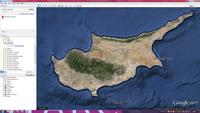 Snapshot of Google Earth showing Cyprus and the area that Ayia Marina is located.
In the case that will be described below, various constraints limit the accessibility to the subject of documentation (Cyprus Buffer Zone) and therefore the recording process should be careful and methodical. The aim of the research reported below was to design and define a methodology for documentation that will take into account a number of restrictions (mainly accessibility to the site, poor working conditions and extreme weather conditions), aiming at gathering data that will be useful for future investigation into conservation / restoration studies, as well as analysis of the architectonic history of the structure. Such documentation includes a throughout recording of the geometry and colour information of the monument (Zhang, Chen, 2001, 935), by means of several techniques described below. Moreover, a complementary aim of the study was to understand which technique is more suitable for such work; consequently, several similar 3D recording techniques (Gabrielli, et al. 2010) were implemented, and their results compared (see below), in order to derive an optimal pipeline for recording as much information as possible, at a resolution and accuracy level suited for consequent scientific analysis, with the adequate metadata and formats to store them in a common repository. As a case study we have chosen the church of Saint Marina, in Derynia, Famagusta district, located in the eastern edge of Cyprus, situated within the Green Line, that is controlled by the United Nations peacekeeping forces in Cyprus.
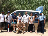
Part of the Saint Marina team with the UN peacekeeping forces
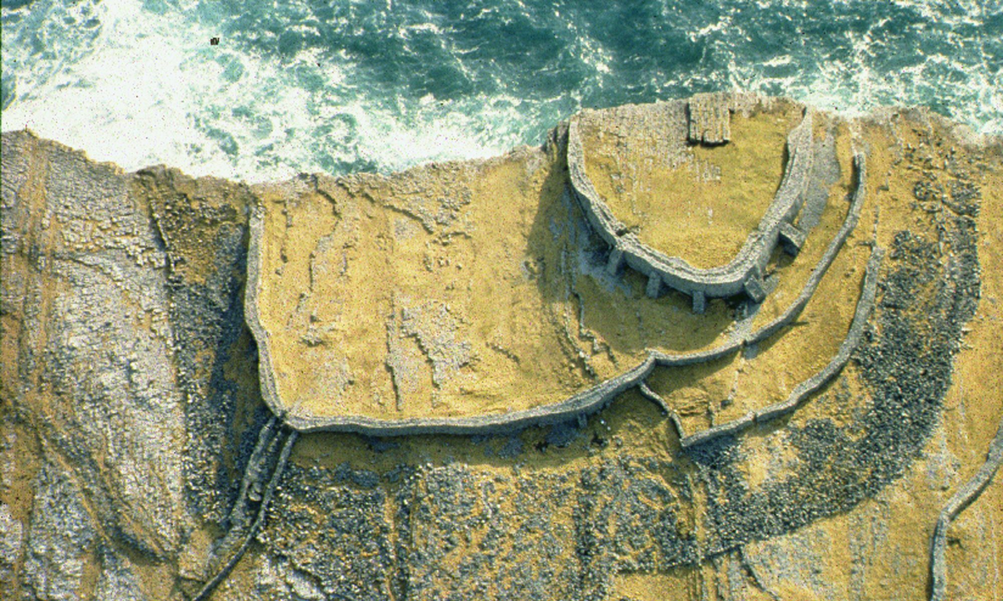
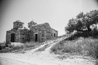
The Saint Marina church was built on top of a small cave, located ca. 2 kilometres east of Derynia village, on the eastern shore of a local stream, within nowadays a barren and abandoned area. There are only dirt roads to access the site and at the location of the church there is no running water or electricity.
According to Victor Karagiannis (Καραγιάννης, 2012), the church was built in the 12th century and it is one of the oldest ones located within the Famagusta region. Originally, the church was a single – domed chapel without a narthex. Later, probably during the 14th century, the chapel was expanded in two phases. Based on later architectonic elements, as well as traces of ruins in the northern part of the church, the church was highly prospered during the 14th century. Still, there is no identification of when or why it was eventually abandoned. Today the church is not accessible by the public as it is located within the United Nations[1] patrolled area[2] . Nevertheless, once a year, when it is the celebration of the name day of Saint Marina, United Nations officers escort the public to the church for a visit. However, this restriction of access to the region tend to destroy both the church and its surrounding landscape since the Five Arches (part of the medieval aqueduct) and several artefacts related to the church are lost in the plants of the streams.
[1] Since 18th October 1977 the church of Agia Marina is under the protection of soldiers of the Austrian Contingent. The soldiers have the possibility to celebrate services, weddings, christenings and ceremonies in the church. The restoration of the church which was in two phases, in 1995 and 1998, was carried out by the Department of Antiquities of Cyprus with the initiative of Derynia Municipality and the financial support of the government and the Holy Archbishop of Cyprus. A celebration commemorating the completion of the work, took place on 14th March 1998. AYIA MARINA – PRAY FOR US (as it is inscribed on a plague within the church).
[2] The church of Ayia Marina is located within the Famagusta buffer zone. “Following the 1974 Turkish invasion of Cyprus, a de facto division of the island into two sections was established, having as a result the separation by the Buffer Zone or Nekri Zoni (Greek for “Dead Zone”). This stripe of land that stretches for more than 180 kilometres across the island has remained inaccessible for about 40 years and since 1963 is patrolled by the United Nations Peacekeeping Force” (Yiakoupi, 2011, 2).
1.1 The church of Agia (Saint) Marina , Derynia
1 Data Collection and methodology
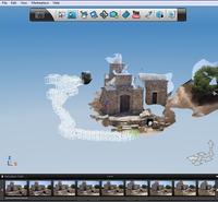
Snapshot from 123D Catch showing the result from 70 images. (SFM)
The survey planning and the digital documentation of the church were quite demanding, as the church is situated in an unattached urban environment. One of the main challenges that the research team had on the site, besides the limitations set by the UN soldiers that were escorting us, were the short time span, the extreme weather conditions (exceptionally hot) as well as the diverse landscape and the topography of the region. In order to document the whole of the church, both interior and exterior, two different photogrammetric techniques, a laser scanner survey and a Gigapan Epic Pro Panoramic Head were carried out. During the post processing for the completion of these tasks, several software were used, such as JRC Reconstructor, Surphaser (laser scanner software), MeshLab, Autodesk 123D, UMap – Menci and Adobe Photoshop Lightroom.
2.1 3D modelling using photogrammetry
Digital documentation and modelling of historic buildings and sites are very important for the virtual recording and preservation of the data. Particularly, the intergradation of photogrammetric data is essentially important in the field of cultural heritage documentation. In addition to this, photogrammetric methods allow the interpretation and measurements from 2D photographic images using the image based modelling. Further in this article there will be an analysis of the two different photogrammetric techniques, explaining the procedure followed during the data acquisition and the final post processed results.
2.1.1 Structure from motion (SFM)
One of the existing methods for creating the 3D model of the church from 2D photographic images is the method of structure from motion (SfM). This process is estimating 3D points from 2D images by identifying common features in sequential images and estimating their trajectories over time (Robertson, Cipolla, 2009). The equipment used on the site was a Canon EOS 6D with a Tamron 24-70 f2.8 lens. 261 pictures were shot by moving around the structure and shifting 30 cm for every picture, in order to cover the entire complex. One of the limitations of this method was that there was no possibility to take pictures from a higher viewpoint.
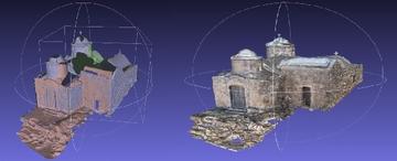 Aligned models from 123D Catch in MeshLab and the final 3D textured model. (SFM)
Consequently, the roof of the church had a poor documentation. Taking pictures for such a process requires that every picture overlaps with the previous one by at least 60% and that the camera is set on a manual mode so as not to have huge differences between images[1] . The post processing of the images was made with the free software of Autodesk , 123D Catch[2] . All the images taken were divided in groups of around 70 pictures of which, 10 common images were used between the groups so as to create 3D models that have an overlapping geometry. This classification of images is useful in aligning and joining the meshes later on. After the models were created they were exported in .obj files and, using MeshLab, they were exported in .ply. After the alignment process, a comparison was made of the quality of meshes of common geometry of the files and removed the meshes with the lowest quality. The next step was to merge the meshes and to close the holes using the Poisson reconstruction filter of MeshLab. The last step was to project images to the geometry in order to assign colours to the vertex and to create the result that are displayed in the figures.
2.1.2 Z-SCAN
“Z-Scan is a 3D scanning instrument for point cloud acquisition” (Menci Software). The main equipment is set up as an apparatus containing a calibrated digital reflex camera with fixed lens, an extendable pole with a tilt mechanism, a tablet with capturing software and the Z-Scan post-processing software based on a multifocal image analysis method. In order to digitally acquire the church, first, some physical obstacles had to be addressed, such as the wild vegetation of the area and the steep inclination of the ground that added more limitations to the capturing procedure. Then, the optimal distance from the monument was estimated at 3 meters, in order to meet the required level of detail. This distance in general should be within 1 – 7 meters away from the monument.
The next step was the capturing of the monument’s surface on a peripheral basis. A specific step of 30 cm was followed according to the selected distance (1/10th of basic distance), in order for the subsequent photos to have a minimum of 60% overlap between them. The exterior walls were separated in three capturing phases; the bottom, the middle and the top level of the wall. For each level a peripheral photo acquisition was performed, extending the pole for about half a meter between different levels. The same procedure was applied to the roof, which was acquired in two main phases. The first two phases captured the monument closely, while the third one captured a panoramic view of the top from further distance, in order to ensure that even the most difficult spots were acquired. It should be noted that for the roof acquisition the pole was extended at about 5 – 7 meters according to the ground altitude, while for the panoramic acquisition was extended up to 8 meters.
After the image acquisition with the UMap software, provided with the Z-Scan[3] , the sequences of photos were processed in order to automatically reconstruct the corresponding point clouds. The format of the imported data was high quality .jpg images. A total of 705 photos were used. Each strip of photos produced a different point cloud, so the results of the roof and the surrounding walls had to be merged together in order to form an overall 3D model. This was achieved in ZMap software, a point cloud editing tool provided also by Menci Software.
The time of acquisition was ca. 2 hours, while the post-processing took about five days, due to the large amount of photos and their high resolution. One limitation that the operator faced was that merging different point clouds increases the overall error each time, adding a smaller, partial error due to a slight merging inaccuracy (in millimetres). Thus, the smaller the amount of photo strips imported, the lesser the additional error produced. Due to the fact that the created model was not scaled, several special targets were used as ground control points (GCPs) and were positioned on several wall sides. Hence, in UMap, a collimation process took place in which these points’ coordinates were imported in a .txt format and processed so that the distance between them indicated the physical distance between targets, thus scaling the model in whole.
When the 3D model was completed, we observed that when a picture was not in a frontal viewpoint according to the orientation of the church, then some parts of the point cloud appeared with some stretched marks or other point misplacements. Thus, a good strategy would be to capture only frontal images every time, using the tilt mechanism of the pole whenever necessary. A main advantage of using ZScan includes its independence from other external hardware and software. ZScan is an autonomous method, as the whole process of data acquisition, reconstruction and demonstration of 3D models can be achieved without using any external processing tools (Bariami, Faka, Georgopoulos, Ioannides, Skarlatos, 2012, 32). The creation of the 3D point cloud is an automated procedure that does not require any user intervention. However, a main disadvantage is its incompatibility with other external post-processing software that would otherwise provide further assistance for the development and completion of the 3D meshes.
2.2 Terrestrial laser scanning (TLS)
The main difference between photogrammetry and laser scanner is the fact that the collection of multiple images for the reconstruction of the church was not necessary. In fact, laser scanner is a tool that has the ability to collect millions of 3D points per second at high levels of accuracy. In the project recorded in this paper, we have used a hemispherical Surphaser Terrestrial Laser Scanner. This scanner is developed with a horizontal view of 360° and a vertical view of 270°, with a speed acquisition of 600,000 thousands up to 1,200.000 points per second (Hermon, Iannone, Amico, 2012, 3). Despite the fact that laser scanner devices have the ability to give detailed surface, the number of scans is always affected by the complexity of subject and its surround landscape. Thus, according to the structural elements of the church the whole sum of scan positions taken was 14. During each position there was a set of 6 targets (useful during the alignment process) of which some were measured in the local system that was created for that purpose. The distance kept from the monument was between 5 – 6 meters. All data points were acquired in a coordinates system with axis line of x, y, z and reflectance. Hence it is important to highlight the fact that the 3D point sets are expressed in grey tones as a reaction to the correspondence reflection of the object’s material, hit by the laser beam. By completing the phase of data acquisition, the density of point clouds was 7 mm and the data weight was of 1.6 GB. This activity lasted approximately 2 hours on site.
The next step is post processing and intergradation from Surphaser to JRC Reconstructor software. Each file format is imported in .ptx format in order to remove any background noise distortion and to filter them for the transformation process from points cloud into a triangulated surface. The point clouds were converted and exported in .ply format for MeshLab[4] . The data weight of all the points after alignment weighted 1.19 GB and recorded an error of 0.0009 mm. The whole post process of the scans until they were converted into a final mesh, for 3 scans (representing the main and left façade of the church), lasted 1 hour (Figures below).
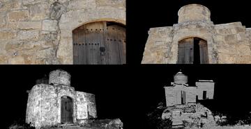
 Snapshots of the initial point cloud parts from UMap software.
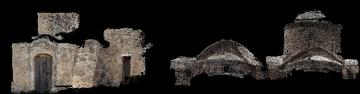
Saint Marina mesh
The upper image is the visualisation of the textured projection on the mesh from TLS (processed in JRC). The image below shows the point clouds from TLS (processed in JRC).
2.3 Total Station and GPS – Georeference of the collected data
For the comparison of results obtained by the different acquisition techniques, a common system of measurements had to be adopted, so a reference survey network was created. Targets were positioned at the two faces of the church during the scanning process and photo acquisition, in order to reference the results on a local system at first and later on for their geo-reference.
A convenient place was selected as a survey station with the aim of visibility of all the Ground Control Points (GSPs). Thus the targets were initially placed and then the TS position was selected. For the measuring of the laser’s targets a Leica Viva TS11 Total Station (TS) was used. After setting up the TS at the base point, the method of setting the orientation was applied. This task is one of the orientation setups of the specific model of TS, which gives the operator the choice of setting up the TS on a known survey station and aiming to a target to set the orientation. Hence, the assumption that the base point was known was taken. After the TS orientation all the GCP’s were measured with the Total Station and referred to the common coordinate system. Either targets or detail points were used as GCP’s, and their measuring was done in reflectorless mode in order for them to be more accurate. The next step was the georeference of the collected data to the Cyprus local system[5] (LTM). For this purpose, three common points were measured with the TS as well as with the GPS (Leica Viva GNSS/GS10-GS15). By measuring the three points with both techniques, the transformation between the Local coordinate System and the Cyprus Geodetic Reference System could be calculated.
Finally, the TS and the GPS give the operator the choice for several export formats like ASCII, custom, .dxf, .xml, Stylesheet and fbk/rw5. The export formats used in this case are at ASCII data and at .dxf data.
2.4 Documentation of the interior of the church
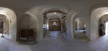
Panoramic image of the interior of the church
The panorama of the interior space of the church was created using a Nikon D800 camera and a Gigapan Epic Pro Panoramic Head. The Epic Pro is a motorized device mounted on a tripod, which hosts a DSLR camera and commands the camera moving it horizontally and vertically with pre-defined increments, taking automatically a picture at every stop position. At any position up to 20 pictures can be taken. The incremental movement is highly reliable: the pan-tilt precision is 0.04 degrees for tilt and 0.12 degrees for pan. In the case study, several tests were made. The best combination of performance and image quality resulted with 78 images only, which were sufficient for the stitching software, GigaPan Stitching software made by the camera producer. Various camera settings were tested, the final one being the following. The lens used was an AF-S NIKKOR 14-24mm f/2.8G ED, set at 14mm focal length. The f-stop was f/10; the shutter speed was set at 1/8. Due to the poor natural lighting of the room, the ISO setting was put to 3600.
The operation took about 15 minutes per panorama. To capture the whole of the church, 6 panoramas were acquired, to be later linked via ‘hot’ points at the connecting part of the room (Figure 8).
2 Comparison and assessment of data
The following table is the result of all the three methods used during the acquisition of data of exterior geometry and colour information of the Saint Marina church.
| Set parameters for documentation | Z-SCAN | Structure from Motion | Terrestrial Laser Scanner |
| Operators | 1 | 1 | 1 |
| Targets | 6/6 | 3/6 | 3/6 |
| Detailed points | 3 | 0 | 0 |
| Data acquisition | 747 (Images) | 261 (Images) | 14 (Scans) |
| Distance from monument | 3 – 5 meters | 2 – 6 meters | 5 – 6 meters |
| Maximum range of acquisition | 7 meters | 6 meters /td> | 25 meters< |
| Minimum range of acquisition | 1 meter | 2 meters | 50 centimetres |
| Format of row data | Raw + JPEG | Raw | C3D |
| Weight of raw data | 5.54 GB | 5.42 GB | 1.6 GB (3 scans) |
| Resolution | High 5 | 472x3648px | Medium |
| Density | 7 mm | 8 mm | 7 mm (3 scans) |
| Weight of process data 7 | 60 MB | 4.77 GB (5 parts) | 1.19 GB (3 scans) |
| Points | 17.000.000 | 11.000.000 | 25.000.000 (3 scans) |
| Alignment error | 3 mm | 1 mm /td> | 0.0009 mm< |
| Equipment price | Eur: 11.800 | Eur: 2.000 | Eur: 60.000 |
| Acquisition time estimation | 2 hours | 2 hours | 2 hours |
| Data post process span | 46 hours | 15 hours | 1 hour (3 scans) |
4 Conclusions
The survey and documentation approaches of historic buildings such as the church of Saint Marina need to be precise and methodical. The advancement of technology nowadays has made several surveying tools accessible for the 2D/3D reconstruction of cultural heritage monuments, through computer vision techniques such as photogrammetry and laser scanning. The combination of these two techniques can gather the advantages provided by each method separately, thus delivering the finest possible results. On one hand, the application of photogrammetry can be a great tool for a quick, automated and accurate geometric textured surface. On the other hand, laser scanner can be the source of reliable high – quality 3D mesh for the interpretation and the assessment of the monument structure. Considering data acquisition, in the case of the laser scanning, the operator has the opportunity to check the collected data in real time (Bariami, Faka, Georgopoulos, Ioannides, Skarlatos, 2012, 32). Thus, after the departure from the field, the collected data are already known, in contrast with the photogrammetric methods where post processing is needed to extract the results. One of the main issues of the laser scanning and Z-Scan approach is that they have to deal with a large amount of data. Therefore, a very powerful workstation computer is needed for the post-processing. In contrast, in the case of SfM, the heavy post-processing happens in the cloud, in Autodesk’s servers, so the resulting files are rather small in size and are easy manageable.[6]
Finally, the work presented in this paper introduces the initial research of the department of STARC for the recording, documentation and interpretation of the buildings’ architectural significance and urban fabric of the Cyprus Buffer Zone. The research is based on the contribution of the STARC to the European funded project 3D ICONS “3D Digitization of Icons of European Architectural and Archaeological Heritage”[7] .
The research approach used by STARC was mainly focused on the application of digital tools that can provide a quick and non – contact monitoring assessment, in order to obtain results that can be further used for analysing the architectural history of the building, evaluating methods of restoration and performing a visual analysis of the surfaces (interior and exterior) for a throughout conservation study. Working in such an environment as presented above requires a full collaboration of many different entities and international bodies, the UN peacekeeping forces (police and military), as well as the office for regulating civil affairs in the Buffer Zone, being essential actors without whom such work cannot be completed (Figure 3).
References
[1] Alshawabkeh Y., Douglas K., Matarya M., Khrisat B., 2011, Combined Photogrammetric Techniques and Computer vision: 2D – 3D recording of Gharissa Jordan, ICCROM.
[2] Bariami G., Faka M., Georgopoulos A., Ioannides M., Skarlatos D. , 2012, Documenting a Unesco WH Site in Cyprus with Complementary Techniques. International Journal of Heritage in the Digital Era, 1, 27-32
[3] Gabrielli R., D’Andrea A., Angelini A., Amico N., Iannone G., 2010, Integrating 3D data acquisition techniques for comprehensive study of the ancient Hellinistic – Roamn Theatre of Paphos, Cyprus, Proceedings of the 38th Conference on Computer Applications and Quantitative Methods in Archaeology, Granada, Spain, 461 – 464.
[4] Hermon S., Iannone G., Amico N., 2012, A three – Dimensional approach to the documentation and analysis of heritage sites – a case study from the Cypriot cultural heritage landscape, 1st International Conference on Best Practices in World Heritage: Archaeology Menorca, Spain, 9 – 13 April 2012.
[5] Kolecka N., 2011, Photo – based 3D scanning VS. laser scanning – competitive data: Acquisition methods for digital terrain modelling of steep mountain slopes, Jagiellonian University.
[6] Robertson D.P., Cipolla R., 2009, Practical Image Processing and Computer Vision: Structure from Motion .
[7] STARC Overview. [Online]. Available at: http://www.cyi.ac.cy/starc.html . [Accessed: 22-Jul-2013].
[8] Yiakoupi K., 2011, Nicosia Buffer Zone: barriers or bridges for urban regeneration? , University of York, 2.
[9] Zhang C., Chen T., 2001, Efficient feature extraction from 2D/3D objects in mesh representation, Proceedings 2001 International Conference on Image Processing, Thessaloniki, 935 – 938 vol. 3
[10] “Photogrammetry and Computer Vision – Menci Software – Image Processing Tech.” [Online]. Available at: http://www.menci.com/index.php?option=com_content&view=article&id=67:zscan&catid=30 . [Accessed: 10-Jul-2013].
[11] Καραγιάννης Β., 2012, Εκκλησία Αγίας Μαρίνας, Δήμος Δερύνειας [Online]. Available at: http://www.deryneia.org.cy/el/episkeptes/ekklisies/agia-marina . [Accessed: 08-Jul-2013].
[12] Τμήμα κτηματολογίου και χωρομετρίας, 2013, έργα και αναπτυξιακό πρόγραμμα. [Online]. Available at: http://www.moi.gov.cy/moi/dls/dls.nsf/All/79064FCB29FDADA5C2256E90005DFAC9?OpenDocument&highlight=ltm. [Accessed: 16-Jul-2013].
[13] 123D Catch tips and tutorials. [Online]. Available at: http://www.123dapp.com/catch/learn . [Accessed: 22-Jul-2013].
[14] 123D Catch. [Online]. Available at: http://www.123dapp.com/catch . [Accessed: 22-Jul-2013].
[15] 3D Icons. [Online]. Available at: http://3dicons-project.eu/ . [Accessed: 19-Jul-2013
[1] http://www.123dapp.com/catch/learn
[2] http://www.123dapp.com/catch
[3] http://www.menci.com/index.php?option=com_content&view=article&id=67:zscan&catid=30
[4] http://meshlab.sourceforge.net/